Disadvantages of vertical capacitor mounting
The previous post in this series (part 2) considered two mountings of the vacuum variable capacitor, a vertical mounting and a horizontal mounting. Previously, I had concluded that "for mechanical simplicity, likely the variable capacitor will/must be mounted in the vertical position for this project," as shown in the below diagram.

Schematically this vertical capacitor mounting would look as follows.

However, as noted in the previous part 2, this mounting has the disadvantage that the current is forced to flow through the narrow, thin connecting straps. These straps might introduce non-negligible RF resistance, hence reducing the antenna's overall radiation. Given the amount of effort that was expended in order to design an easy-to-construct, low-resistance conductor for the loop (the 10 cm^2 cross-section conductor, equivalent to a 10 cm-diameter round copper conductor), it seems counter-productive to introduce a high-resistance, narrow strap into the current path.
It might be argued that the shortness of the strap would limit its resistance and hence limit its overall detrimental effect. Nevertheless, I remained concerned about this approach; if we consider the action of a fuse, high current is forced through a very short and very narrow path. And if the current is high enough, the fuse burns out. So even if the current path is very short, as in a fuse, an overly-narrow conductor can have enough resistance to undesirably dissipate energy as heat.
Furthermore, with the vertical capacitor mounting, the loop current is forced to change direction from horizontal to vertical as it flows from the horizontal loop element, through the straps, then vertically through the capacitor. The forcing of the current flow through the straps, and the changing of RF direction from horizontal to vertical, might introduce significant losses into the antenna.
Therefore, more detailed study was done of the horizontal capacitor arrangement, where the capacitor is mounted horizontally in-line with the current flow.
Horizontal capacitor mounting with embedded motor
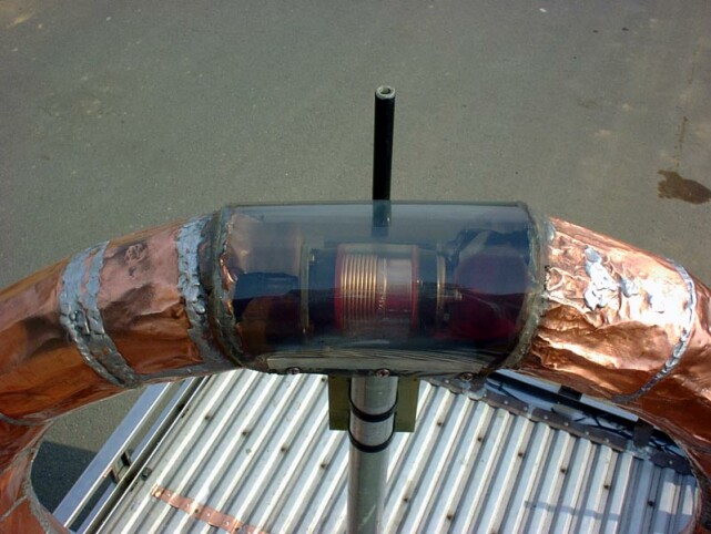
Horizontal mounting of the capacitor could look something like the following picture.

However, we still need to consider how to drive the variable capacitor with a motor. With the horizontal, in-line capacitor mounting, the tuning shaft for the variable capacitor is located in the interior of the loop conductor. Therefore, one approach is to mount the motor also inside the loop conductor, immediately next to the shaft of the tuning capacitor, so that the motor can directly drive the capacitor shaft. Schematically this would look as shown in the following diagram.

This horizontal, in-line mounting of the capacitor should result in minimal loss, as the current is not forced to change direction, and furthermore the diameter of the conductor remains as wide as possible, tapering smoothly from the wide-diameter loop conductor to the somewhat smaller-diameter connector that is clamped onto the variable capacitor's terminals.
As mentioned before, successful examples of this style of mounting are shown in JL1BOH's loop, at http://www.aa5tb.com/jl1boh_04.jpg (which is explained at the bottom of AA5TB's page http://www.aa5tb.com/loop.html), and in in IZ2JGC's loop antenna as shown at https://plus.google.com/u/0/117232231941836334584/posts/D2v9Ht7yzNF.
Disadvantages: motor servicing, and possible loop imbalance
Nevertheless, a fundamental difficulty with this construction is that the motor needs to be embedded inside the loop conductor itself. This raises two concerns:
- The motor has a finite lifetime and will eventually fail. If the motor is embedded within the solid loop conductor, removing it for replacement will be very difficult, perhaps requiring cutting apart and dismantling of parts of the loop conductor.
- Mounting of the motor next to the variable capacitor may cause some unbalancing of the loop. In particular, the long motor control wires (providing DC to the motor) must run away from the motor body, through the interior of the loop, and exiting somewhere near the center of the bottom segment of the loop. Theoretically, these wires should not have any induced RF currents, because they are located on the interior of the loop conductor where no or minimal RF current should flow.
However, in my particular design, the loop conductor thickness will be moderately thin (0.2 mm thickness or 8 skin depths at 7 MHz), and furthermore the loop conductor will be segmented, as it will consist of 4 separate strips of copper flashing mounted on each of the 4 faces of the square-cross-section support tubes. The seams along the corners of the square-cross-section tubes will not be soldered, meaning that the interior of the tube is almost, but not completely, shielded from the electromagnetic field external to the tube.
The possibility of some RF on the interior of the tube means that the long motor control wires, running from the top of the loop conductor's interior to the bottom of the loop conductor's interior, might undesirably carry some induced RF currents, which would undesirably introduce imbalance into the loop. Now, of course, no real-world loop can ever be perfectly balanced (because the loop itself must be mounted over ground with asymmetrical properties, in a surrounding environment that is also asymmetrical), but still it is desirable to eliminate any unbalancing factors that can be eliminated during the design of the loop.
Mounting the capacitor horizontally, but with the motor outside of the loop conductor's interior
The next design considered was to mount the capacitor horizontally and in-line with the loop, but mounting the motor outside of the loop. Schematically this would look as shown in the following diagram.

- A right-angle gear mechanism is required to change the direction of required shaft torque from horizontal to vertical. This right-angle gear mechanism is depicted above as the grey-coloured, L-shaped connector. Details of the gear mechanism are described below in a following section.
- A small hole must be cut in the bottom surface of the loop conductor, to allow the shaft to exit from the interior to the exterior of the loop conductor. This small hole can be expected to very slightly increase the RF resistance of the loop conductor, but its detrimental effect should be very small (especially compared to the detrimental effect and expected high RF resistance of thin connecting straps as would be required with vertical capacitor mounting, as explained earlier).
This design is starting to look almost ideal. However, the motor is mounted at a position that is offset from the center of the loop, which again is undesirable and might introduce some loop imbalance.
Final design: Horizontal capacitor mounting, three right-angle gear mechanisms, and centrally-located motor at bottom of loop
Taking into account all of the above yields the following design.

External mounting of the motor also allows easy replacement of the motor when it fails.
Also, the external motor mounting allows enough space around the motor to install a limit switch mechanism. For example, a long, plastic, threaded rod could form part of the central vertical plastic shaft extending from the motor. Then, a plastic nut on the threaded rod could form a shuttle which, with appropriate constraining to guiding side rails, would slide up and down the threaded rod as the motor was rotated clockwise and counter-clockwise. Then, limit switches could be mounted at near the top and bottom of the threaded rod, corresponding to the shuttle position just before the extremes of the allowed capacitor rotation are reached. The limit switches could be used (perhaps in combination with relays) to disable the current to the motor when the limit is reached, preventing undesirable over-torquing of the capacitor shaft when it is already at the end of its allowed travel.
Finally, from the above diagram, we can see that we need not one, but three right-angle gear mechanisms, in order to transmit the rotational motion from the centrally-located vertical motor shaft onto the horizontally-mounted and off-center capacitor shaft.
The right-angle gear mechanism
The final question is what, exactly, to use for the three right-angle gear mechanisms, which are required to change the axis of the rotational motion.
To implement a right-angle gear mechanism capable of changing the axis of rotation by 90 degrees, three different approaches were considered.
- Use a pair of gears mounted at 90-degrees. The gears could either be spur gears (with protruding teeth) or peg gears (forming a crown-and-lantern gear mechanism).
Advantage: The gears could be hand-constructed out of low-loss dielectric material such as polyethylene.
Disadvantages: Constructed gears would likely be rather large and difficult to fit inside the interior of the loop conductor. Some backlash would be inevitable in the hand-cut gears. Moreover, reliability of the gears could be questionable -- glued-on pegs might break off, teeth might no longer mesh, and over the operational lifetime of the loop the entire hand-constructed gear assembly might break, slip, twist, bend, or slant in undesirable ways such that it no longer functions properly. Because the top-most gear mechanism must be mounted inside the loop conductor, its reliability is very important because any maintenance due to malfunction or breakage would, just like an internally-mounted motor, require extremely tedious dismantling of the solid loop structure. - Use a pulley-and-belt mechanism.
Advantages: Hand construction and assembly might be easier and more reliable than attempting to construct a gear-based mechanism. And again, materials could be selected to be low-loss dielectrics.
Disadvantage: High tension on the belt would be required in order to properly transfer torque from one axis to another. This would place considerable strain on the surrounding loop structure. However, the entire loop support structure (corrugated plastic) is designed to be lightweight, and might not survive the stress of one -- let alone three -- highly-tensioned belts. The corrugated plastic support structure might buckle and collapse on itself when subject to such high belt tension. - Use a commercially-available right-angle drill adapter.
Advantages: Physical size is much smaller than would be possible with hand-constructed gears. Backlash is minimal. Reliability can be expected to be very high, with breakage or misalignment unlikely over the lifetime of the loop antenna.
Disadvantage: The gears and small shaft protrusions are all made of metal. Because these gear mechanisms will be located near the intense electric field generated around the capacitor, ideally these mechanisms should be non-metallic, low-loss dielectrics.
After much consideration, the decision was made to use the commercially-available right-angle drill adapters.
Because the right-angle adapters are metallic and mounted near the capacitor with its intense electric field, it is conceivable that RF currents could be induced in the metallic gear structures. Theoretically, these currents could unbalance the loop and could also cause undesirable resistive losses as these induced currents flow through the poorly-conducting metallic gear structures. However, in practice, I assume that the very small size of these gear mechanisms (compared to the loop size) will mean that almost no RF current will be induced into the right-angle adapters.
Furthermore, and as a specific counter-measure against unwanted RF currents flowing in the adapters, all mechanical connections between the three right-angle adapters will be made with plastic shafts. In particular, long connecting metal shafts must be avoided, as they could be more likely to have currents induced in them by the electric field. By using only plastic shafts to connect the three right-angle adapters, we should be able to greatly minimise the amount of RF current induced into the metallic gear structures.
Details of the commercially-available, right-angle drill adapters
Below is a picture of the three right-angle drill adapters that were purchased.

Below is a video showing the planned configuration of the three right-angle drill adapters, in order to translate the rotation along the vertical axis to rotation along a horizontal axis, at an position offset from the original vertical axis.
https://youtu.be/SVO3ds2qK3o
https://youtu.be/SVO3ds2qK3o
The video shows metal shafts being used, but these will be replaced during the actual construction with plastic shafts.