2017年9月30日土曜日

A 1-meter-diameter small transmitting loop for 7 MHz: part 2

This post details the construction of a 1 square meter plastic support frame for a small transmitting loop antenna. A previous post described the vacuum variable capacitor that is planned for this project.

Idea: Large-diameter plastic support frame surrounded by thin layer of copper

To ensure maximum current flow through the loop conductor, ideally a large-diameter copper tube would be used for the loop conductor. For this project I wanted a conductor diameter of 10 cm. However, 10-cm-diameter copper tube is not available for me to purchase locally, and even if it were, I lack the equipment needed to form a loop conductor from such a thick copper tube; this would require either bending the 10-cm-diameter copper tube into a loop, or soldering several short segments together to form a loop-like shape. Either bending or soldering such a huge-diameter copper tube would require specialised equipment.

As an alternative approach, I decided to construct a plastic support frame consisting of 10-cm-diameter plastic tubes. The surface of this support frame will then be covered by a thin layer of copper sheet metal, to form a large-diameter conductive copper tube.

A later article will show how to apply the conductive copper sheet on top of the plastic support frame.

Square cross section instead of circular cross section

The 10-cm-diameter plastic tubes were constructed manually (see next section), because no suitably light and strong 10-cm-diameter plastic tubes could be found.

For ease of construction, the 10-cm-diameter plastic tubes have a square cross section instead of a round cross section. This will make easier the subsequent application of the conductive copper sheet, as the copper sheet can be affixed to the flat tube surface, which is easier than attempting to affix a copper sheet to a round tube surface. 

Furthermore, the RF resistance of a square-cross-section tube (having a side length of r centimeters) is the same as the RF resistance of an equivalent-diameter round-cross-section tube having radius of r centimeters. This result was published by H. A. Wheeler in 1955, in an article titled "Skin Resistance of a Transmission-Line Conductor of Polygon Cross Section". A quote from Wheeler's abstract follows.
If a conductor cross section is any straight-sided polygon that can be circumscribed on a circle, it is found to have the same skin resistance as a conductor whose cross section is this circle. For example, a square wire has the same resistance as a round wire of the same radius, though the square perimeter is 4/pi times as great. 

Finally, and most reliably, the equivalent result can be verified by finite-element method (FEM) electromagnetic field simulation software, which allows not only computation of the RF resistance of a square-cross-section conductor, but also allows computation and visualisation of the actual RF current distribution within the conductor. A future article will describe a FEM simulation showing the equivalent RF resistance of a square-cross-section conductor and an equivalent-diameter round-cross-section conductor.

As a sneak preview of the upcoming FEM analysis, below are some screenshots of my previously-conducted analysis of current density in a square-cross-section conductor consisting of four separate flat copper sheets. The simulation results need to be checked for plausibility and checked against analytical predictions, but current results initially seem quite plausible.


Constructing the plastic tubes

A significant challenge was finding tube material that was sufficiently lightweight to allow easy cutting and joining with hand tools, but at the same time was sufficiently strong to support itself and the weight of a vacuum variable capacitor at the top of the loop.

Ordinary 10-cm-diameter PVC pipe was ruled out for two reasons: (1) it is too heavy and unwieldy for this project and, more importantly, (2) its round cross section would make surface application of copper flashing quite difficult. 

I settled upon using corrugated plastic sheets that were available from my local hardware store in dimensions of 91 cm x 45 cm. The thickness of the corrugated sheet is about 2 mm. This construction is extremely lightweight, while the corrugation provides some degree of structural strength.


The plastic sheet was lightly scored, at 10-cm intervals, with the blunt tip of a pen.


The sheet was then folded along the scored lines, to form a square-cross-section tube.


Next the placement of the vacuum variable capacitor was investigated. Below, the vacuum variable capacitor is placed inline with the top tube. This arrangement would probably result in the lowest RF resistance (allowing the current to flow directly from the tube to the variable capacitor with minimal change of direction). 


However, the above inline method of capacitor mounting is challenging to construct because it provides no easy way of removing the variable capacitor, requiring the loop to be constructed bit by bit around the variable capacitor, eventually resulting in a solid structure encasing the capacitor. This was deemed too difficult for this project. Nevertheless, an example of a successful construction of this type can be seen in JL1BOH's loop, at http://www.aa5tb.com/jl1boh_04.jpg, which is explained at the bottom of AA5TB's page http://www.aa5tb.com/loop.html. Another successful construction of this type, using inline horizontal mounting of the vacuum variable capacitor, can be seen in IZ2JGC's loop antenna here: https://plus.google.com/u/0/117232231941836334584/posts/D2v9Ht7yzNF.

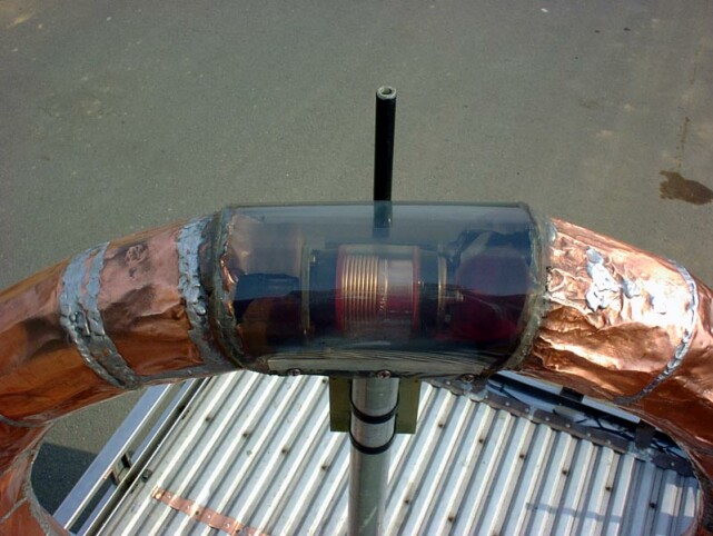
Below, the traditional vertical orientation of the vacuum variable capacitor is attempted. This could result in a slight increase in RF resistance as all the RF current from the tube is forced to flow in the small and thin straps that connect to the variable capacitor. One representative strap is shown below by the yellow strip of paper. In addition to the strap resistance, the RF current is also forced to change direction from horizontal flow in the tubes, to vertical flow through the capacitor. Possibly, a future article may investigate numerical simulations and visualisation of the RF current density when the current is forced to flow from the wide-diameter tube into the small, thin strap. In any event, for mechanical simplicity, likely the variable capacitor will/must be mounted in the vertical position for this project.


Next, the remaining plastic sheet was cut into corner-shaped pieces to join the tubes together. In the below image, the yellow paper indicates the size of one corner piece.


The pattern for two corner pieces looks as follows.


Cutting and separating the corner pieces is shown below. Note the uneven edges along the connecting seam still need to be trimmed to be straight.


The final collection of 8 corner pieces is shown below.


Affixing the straight tube segments to the corner pieces with double-sided tape gives a loop-like shape.


The loop is strong enough to support itself, though slight sag is evident at the top due to the gap in the loop.


Next steps

The structural strength at the corners should be improved, as currently the corner supports only consist of two flat L-shaped sheets.

The current taped-together construction should be redone with glue. An appropriate glue must be investigated.

It must be investigated how to support the heavy vacuum variable capacitor at the top gap of the loop. Possibly, a separate tripod-like stand and vertical pole (spine) could support the heavy capacitor independently. Then, some sort of arms extending from the spine could support the loop. The loop would then be laid or "hung" on top of the arms extending from the spine. Alternatively, some vertical or diagonal support braces could be introduced on each side of the gap to prevent sagging. It must however be kept in mind that the structural strength of the corrugated plastic -- even with additional bracing -- might not be great enough to withstand the stress caused by the weight of the vacuum variable capacitor. The corrugated plastic walls of the tubes (that would need to bear the force of the bracing) could buckle or collapse if subjected to too much weight. This points to a separate spine as the likely solution, so that the spine would bear the weight of the capacitor and the loop, thus freeing the fragile loop from bearing any weight, and only requiring the thin-walled loop to be sturdy enough to avoid collapsing on itself -- which it already is.

Once the loop structure and supporting structure have been finalised, the next big step will be applying an electrically-continuous copper sheet to each of the four flat faces of the loop surface.

2017年8月16日水曜日

Wireless audio and remote rig control, part 2

This article is a brief report on a low-latency audio streaming setup using the Mumble software.

A previous article described remote control, via PC, of a commercial superheterodyne receiver, and streaming the audio from that receiver over wifi for reception at another nearby location. This allows placing the receiver and antenna in a high-signal area (outdoors on a balcony), while placing the listening PC in a convenient indoor location. The use of wifi means that no cabling is necessary between the outdoor PC and the indoor PC.

However, the previous article's solution (using ffmpeg, JACK, and VLC software) achieved a best-case latency of about 1-2 seconds. In other words, the time delay between the actual audio output at the outdoor receiver, and that same audio output being received, decoded, and played back by the indoor PC, was about 1-2 seconds.

I was successful in reducing the latency by using a low-latency voice-over-IP software package called Mumble. This post briefly describes the background, procedure, and results.

Background


I have an HF-capable RTL-SDR receiver (a small USB dongle plus a homebrew upconverter) that is controlled by a PC running the gqrx software on Linux. The RTL-SDR, the PC, and a broadband loop antenna are sited in a high-signal location, outdoors on a balcony.

By operating the gqrx software on the outdoor PC, it is possible to control the RTL-SDR hardware and instantly to receive any frequency within its reception range. Because I am using a broadband antenna in combination with a broadband HF upconverter, I can receive any HF frequency from 0-30 MHz merely by operating the gqrx software. Furthermore, the RTL-SDR has a wide reception bandwidth (maximum of about 2.4 MHz), and gqrx provides a graphical display of spectrum activity, making it possible to see at a glance all spectrum activity (i.e. all signals) within the reception bandwidth. This makes searching for signals an audio-visual activity rather than a purely auditory activity as with traditional radios that have a narrow-band IF filter.

However, it is inconvenient to be operating the PC outdoors on the balcony when I want to listen to HF signals with the RTL-SDR. Therefore, my goal was to remotely control the outdoor PC via wifi, and to remotely receive the audio via wifi from the outdoor receiver, for final listening on an indoor PC.

First attempt: rtl_tcp and too-high latency


The RTL-SDR is a software-defined radio that makes the I/Q (in-phase and quadrature) data directly available for processing in software. My first attempt was to stream the raw I/Q data directly over the network, using the rtl_tcp program on the outdoor PC. The indoor PC then received the data via wifi and processed the signals in the gqrx software. While this worked, it had two major problems:

  1. Latency was very high, on the order of 5 seconds or more. This is simply due to the massive amount of I/Q data that is being sent over wifi. Tests with a sampling rate of 2.4 million samples per second -- where each sample is 2 bytes -- yielded unusably high latency and frequent gaps/stuttering in the audio on the indoor receiving PC. Reducing the sample rate to the minimum of about 200 kHz reduced latency and stuttering, but latency was still too high to be comfortable (2 seconds or more). Furthermore, reducing the sample rate also undesirably reduced the visible bandwidth in the software's waterfall display, negating one of the benefits of using a wideband SDR.
  2. The gqrx software seemed to have some bugs when decoding network data coming in from rtl_tcp. When running gqrx on the indoor PC, I noticed odd spurious signals such as the same station appearing at two frequencies separated by only a few-tens-of-kHz offset. These spurious signals were not present when running gqrx on the outdoor PC to directly (not over wifi) decode the I/Q signals from the hardware dongle. Some related links describing similar problems are as follows: https://www.reddit.com/r/RTLSDR/comments/4ygu66/is_anyone_using_rtl_tcp_and_gqrx_successfully/ , https://github.com/csete/gqrx/issues/402 . According to the last link, a workaround should be provided in gqrx version 2.7, but the version included in my Linux distribution was 2.6.

Second attempt: Use gqrx UDP audio streaming


The gqrx software has the ability to stream raw audio over UDP. By streaming only the decoded audio with 48 kHz bandwidth, instead of the entire 2.4-MHz-wide reception bandwidth, I hoped to substantially reduce the network traffic and hence reduce latency and playback stuttering.

I ran gqrx on the outdoor PC, and configured gqrx to streamed the audio over UDP to the indoor PC. Also, a VNC server was run on the outdoor PC to share its screen over the network.

On the indoor PC, I ran a VNC client to be able to see the outdoor PC's screen and to be able to operate the remotely-running gqrx software. Then, I used the following command to play the audio (being streamed via gqrx) with minimum latency on the indoor PC.

nc -l -u 7355 | aplay -r 48k -f S16_LE -t raw -c 1-B 300000

The last parameter of -B 300000 specifies a 300 ms buffer. Reducing this buffer value reduces the latency, but then increases the chance of gaps or stuttering in the played back audio if the transmitting (outdoor) PC cannot deliver data quickly enough over the wifi network. Increasing this buffer value reduces stuttering but of course increases latency.

Unfortunately, even with 300 ms of latency, the audio would still sometimes stutter, indicating a lack of incoming data for playback. In other words, the streamed audio from gqrx still was overburdening my wifi network (which uses an old PC with two wireless network cards as a router).

Third and successful attempt: use Mumble voice-over-IP software


AG1LE describes how he configured Mumble for remote streaming of audio from an amateur radio receiver. I decided to try Mumble as well, reasoning that Mumble would be able to compress the audio before network transmission, leading to further reduction in network load and further reduction in latency.

The setup was as follows. On the outdoor PC, I used:
  • VNC server, to share screen over wifi.
  • The RTL-SDR USB dongle, connected to a USB port.
  • gqrx software, which demodulates RF signals from the RTL-SDR and produces audio output directed to the PC's audio output hardware.
  • A physical audio patch cable running from the PC's headphone output into the PC's microphone input.
  • Mumble server software to accept Mumble clients and route voice (audio) data over the network.
  • A Mumble client, taking voice (audio) input from the PC's microphone input. Mumble client was configured as follows:
    • Noise suppression disabled (enabling it leads to an over-aggressive AGC-like action where slightly fading shortwave signals will be miscategorised as noise and completely suppressed)
    • Transmission mode set to "continuous" (instead of "voice activity" or "push to talk")
    • Compression quality (slider) set to middle position
On the indoor PC, I used:
  • A Mumble client to receive the audio being transmitted by the outdoor PC's Mumble client.
  • A VNC client to see the outdoor PC's screen and to operate the gqrx software.
The results were as follows:
  • Latency was greatly reduced, to less than 0.5 seconds. It is possible to operate the remote (outdoor) PC via the networked VNC client, and to hear the corresponding audio changes (e.g. when a new frequency was selected in the gqrx software) on the indoor PC almost immediately. The low latency makes operation of the remotely-running gqrx SDR software feel responsive and real-time.
  • Latency never increases over time, but instead stays at a very low level over the entire streaming session.
  • Playback gaps/stuttering were almost completely eliminated.
  • Audio quality is slightly degraded by the compression. The audio sounds somewhat "tinny". Mumble is aimed at voice chat and not high-fidelity reproduction. Nevertheless, the audio quality is perfectly acceptable for listening to shortwave AM broadcasts and amateur SSB and CW transmissions. However, for amateur data transmissions such as RTTY or JT65, it is likely that the audio compression could prevent decoding of the data on the indoor PC. If data decoding is necessary, it should be done on the outdoor PC, where the raw uncompressed audio is available.

Next steps


  • Investigate how to eliminate the audio patch cable. gqrx is already decoding the data into digital form. By playing it back over the audio output, then physically routing this (with an audio patch cable) back into the audio input, we are introducing extra digital-to-analog and analog-to-digital conversion steps. It would be better to directly pipe the gqrx digital data into the Mumble server. However, it is not clear if this is easily possible. Using the JACK software might be an option to reroute the audio data streams, but JACK does not seem to work with gqrx. Pulseaudio also seems to have some capability for rerouting audio data streams.
  • Investigate throttling (restricting) the amount of network traffic used by the VNC screen-sharing software. Although the network usage of the audio stream (from outdoor PC to indoor PC) is throttled by the Mumble client settings, the network usage of the VNC screen-sharing software (again from outdoor PC to indoor PC) is not throttled and therefore may be consuming too much network bandwidth, which ultimately could lead to network congestion and delayed or stuttering audio. By explicitly limiting the amount of network traffic that VNC is allowed to use, this could ensure sufficient bandwidth for low-latency, non-stuttering audio. The "trickle" command on Linux may be one easy way to achieve the bandwidth throttling. Alternatively, Linux firewall rules and traffic shaping might be used.
  • Improve my local network infrastructure by upgrading my old wifi hardware to a dedicated hardware router (instead of a repurposed old PC) that supports the latest and fastest wifi standards. This might require also buying newer, faster wifi hardware (USB dongles) for the outdoor PC and indoor PC, because the built-in wifi hardware of the outdoor PC and the indoor PC might not support the fastest wifi standards.
  • Investigate interfering wifi signals (caused by other nearby wifi devices not under my control) and plan location of my wifi hardware  (router, transmitting PC, receiving PC) accordingly. Possibly, add a second intermediate wifi router if needed.

2017年7月30日日曜日

RTL-SDR upconversion with diode-ring mixer: part 2

This post describes an improved version of my homebrew, one-transistor RTL-SDR upconverter, including a circuit diagram and videos of the unit in operation.

Cleaning up the oscillator signal


The previous version of my homebrew RTL-SDR HF upconverter used a Pierce crystal oscillator with a crystal that was marked as 49.8 MHz.

Monitoring on a nearby receiver revealed that the oscillator was generating signal energy at 16.6 MHz and 33.2 MHz as well as at 49.8 MHz. Therefore, the simple Pierce oscillator was exciting the crystal at its fundamental frequency, with the desired LO energy at 49.8 MHz being merely a side-effect. So the LO was producing signal energy at many harmonically-related frequencies, which will introduce a host of unwanted mixing products at the mixer output, greatly increasing spurious signals and IMD.

To force the oscillator to oscillate only at the desired overtone frequency, I changed the oscillator topology to a common-base Colpitts, using the crystal to ground the base at RF. An LC tank circuit in the collector is tuned to approximately 49.8 MHz to prevent gain all other frequencies, in particular the fundamental frequency of the crystal. In practice, the base was first grounded with a 100 nF capacitor and the LC circuit tuned (by removing/stretching/squashing the turns on L1) to approximately 49.8 MHz. The oscillator's frequency could be monitored by watching the waterfall display on the gqrx SDR software (or alternatively by listening on a separate VHF receiver for the radiated signal). After adjusting L1 for oscillation at approximately 49.8 MHz, then the grounding base capacitor was replaced with the 49.8 MHz crystal. Finally, monitoring on a nearby receiver revealed an oscillator signal only at 49.8 MHz, but not at 16.6 MHz or 33.2 MHz -- just as desired.

The current circuit diagram is as follows.


I then connected the oscillator to the RF input port of the mixer, through a 100 nF capacitor. Unfortunately, this stopped oscillation. A 1000 pF capacitor allowed oscillation and was used.

Results


Reception results (using my M0AYF-designed active loop antenna -- reference: http://www.qsl.net/m0ayf/active-loop-receiving-antenna.html) were much better than before with far fewer spurious signals. Shortwave signals were where they were supposed to be (WWV at 5, 10, and 15 MHz, ham signals at 7 and 14 MHz). Furthermore, occasionally ionosonde signals could be seen, and the ionosonde signal progressed from low frequency to high frequency on the software's waterfall display. If many spurious mixing products were present, we would expect mirror images or duplicate images of the ionosonde signal, but none were observed, indicating the HF upconverter is mostly working.

Here is a short video showing the reception results. You can see ionosonde signals at 01:35 and 02:33 in the video.

The video also shows the effect of adjusting the LNA gain, starting at 02:20. If the gain is too high, spurious signals and IMD start to appear. If the gain is too low, sensitivity suffers.


Here is a short video showing the physical layout of the completed circuit.


Next steps

The crystal oscillator signal seems to be noisy, as evidenced by raspy tones when listening to CW signals. I suspect the 5V voltage taken from the USB hub is not sufficiently filtered for oscillator use. I will investigate voltage regulation and/or filtering on the Vcc line.

I still have no way of measuring the oscillator output power (e.g. an RF probe). Most likely, the oscillator is not delivering the required 7 dBm into the mixer's LO port. Nevertheless, the converter seems to be working reasonably well, so perhaps the LO drive is sufficient for casual listening purposes. If possible, I would prefer to keep the circuit simple (just 1 transistor) rather than adding more amplifier/buffer stages after the LO.

Some minor FM broadcast interference was still audible at some locations in the shortwave band, but the interference is limited to a few specific frequencies. A simple LPF on the RF port could fix this.

Addendum 2017-08-05

After playing with my upconverter a few days, I have a few additions and corrections to this article.


Correction: The LO is not noisy


I previously mentioned that the crystal oscillator seemed to be noisy due to raspy-sounding CW signals. It turns out that the oscillator is fine and is generating a clean signal.

The debugging process was first to listen to the radiated LO signal on a nearby receiver in CW mode. The radiated signal sounded very clean, which was puzzling because I suspected a dirty LO signal. Nevertheless, I thought it might be remotely possible that while the radiated signal was clean, perhaps the signal tapped off of the emitter (and fed into the mixer) might be dirty or distorted. The next step was to power the LO from a battery instead of from the USB power, to see if a dirty supply voltage was distorting the LO signal. However, powering the LO from a battery yielded no change in the quality of CW signals. Next, I powered the active antenna from a battery as well, instead of from an AC adapter. That also yielded no change. Therefore, either (1) the problem was due to noise somehow getting into the oscillator via another route, or (2) the problem had nothing to do with the oscillator. It turns out that (2) was the case.

The raspy tones I heard when listening to CW were due to a too-high sample rate being set in the gqrx SDR software. I was originally using a sample rate of 2.8 million samples per second. I reduced this to 2.4 million samples per second, and then the CW signals sounded pure and clean as they should. Probably, with the higher sample rate of 2.8 MS/s some samples were getting lost, which led to the unclean-sounding CW signals.


Perhaps the LO drive is sufficient


The web page of VK6FH at http://www.vk6fh.com/vk6fh/RF%20MIXERSdiode.htm describes some of the consequences of reduced LO drive level for diode ring mixers. A quote from that page follows, describing the effect of lower LO drive for commercially-available diode ring mixers.
Some designers shy away from using these passive double balanced mixers (DBM) because of the fairly high LO drive required.  However, they can be used successfully with lower drive levels. The efffect will be the conversion loss and port-to-port isolation (defined below) will get worse, but since we are using these devices at the very bottom of their 1GHz range, the effects are minimal. LEVEL 7 mixers can be used by driving the LO port with a single transistor crystal oscillator, delivering about +3dBm which is 0.32V rms into 50 ohms (2mW ) with good results.

VK6FH's web page presents a table showing the effects of reducing the LO drive from +7 dBm to +3 dBm -- slightly more conversion loss, and slightly worse port-port isolation. But these effects are not catastrophic, especially for a casual hobbyist receiver as this one is.

Also note that VK6FH specifically says that a single-transistor crystal oscillator (such as the one I am using) is capable of driving a level-7 mixer as long as the oscillator can provide about 0.32V RMS into 50 ohms.

So the question remains: is my single-transistor oscillator capable of delivering 0.32V RMS into 50 ohms? I lack the test equipment to test this currently. However, before building the oscillator, I did simulate it in LTspice and adjusted the circuit constants such that the simulated oscillator delivered more than 0.32V RMS into 50 ohms. Given the simulation results, and given the good reception results in practice, I see no need to attempt to increase the LO output (which would undesirably increase the circuit complexity).

A future article will explain the LTspice simulation of the local oscillator circuit.

---

2022-03-18 update

I noticed a jump in traffic, and it seems that this article was linked from hackaday.com again. :-) So here is an updated picture of the converter. I rebuilt it on a smaller piece of copper foil, affixed to a bit of cardboard. One of these days I may make a small 3D-printed enclosure for it.


2017年7月23日日曜日

RTL-SDR upconversion with diode ring mixer: part 1

This post describes my first experiments with using a homebrew upconverter to receive HF on an RTL-SDR dongle.

Problems with direct sampling


A previous post described my experiments with RTL-SDR direct sampling, where a short connector wire is connected directly to the RTL2832 chip, bypassing the internal device's tuner. The connector wire is routed outside the plastic case of the RTL-SDR dongle, and a wire antenna is then connected to this short connector wire.

I encountered two major problems with this approach:

  1. Because this approach bypasses, in hardware, the internal tuner of the RTL-SDR device, the signal is no longer routed through the device's software-controllable low-noise amplifier (LNA) stage. Therefore, it is no longer possible to control the signal gain via software. This is disadvantageous because with a broadband front-end, it is essential to control signal levels to minimize IMD.
  2. Even with no wire antenna connected, with only the short connector wire in place, severe breakthrough of broadcast FM stations was audible in shortwave frequency bands. Therefore, avoiding FM breakthrough with the direct sampling approach would require more careful wire routing, use of shielded conductors, adding extra shielding inside on the existing and small PCB, etc. This greatly complicates the design process.

Onward, and upward

I decided to try an upconversion approach instead, where the entire HF band from 0-30 MHz is converted upwards by about 50 MHz, to lie between 50 and 80 MHz, which is then directly receivable by the device.

I chose 50 MHz (approximately) because I happened to have a 49.8 MHz crystal available in my parts bin, purchased some time ago because I vaguely thought it might turn out to be useful someday. And indeed, it did turn out to be useful.

Constructing the oscillator


I built a simple 49.8-MHz Pierce oscillator roughly following the guidelines in http://www.rakon.com/component/docman/doc_download/234-single-transistor-crystal-oscillator-circuits. I used a 2N3904 transistor, which  is barely suitable in this application. The transition frequency (ft) of the 2N3904 is about 250 MHz, and generally ft should be 10x greater than the desired oscillation frequency of 50 MHz, so ideally we should use a transistor with an ft of 500 MHz.

Power for the oscillator comes from a USB port of a USB hub, which supplies 5 volts, though the document above shows oscillators designed for a 3-volt supply.

Due to the unknown crystal parameters, my use of a 5-volt instead of a 3-volt supply, and slight deviations in my design from the recommended component values, I have no idea exactly how much power this oscillator is capable of delivering. As the oscillator is intended to drive a diode-ring mixer, the oscillator should provide a 7 dBm signal into the mixer's LO port.

I strongly suspected that this single-transistor oscillator would not provide enough LO drive to properly drive the mixer. Nevertheless, I proceeded to construct the rest of the upconverter circuit, assuming the circuit would work well enough for me to hear something.

Constructing the mixer


Next I constructed the mixer. From my bag of about 100 1N4148 diodes, I selected a handful and picked 4 diodes that had roughly the same forward-voltage drop, as measured by a multimeter.

The 4 diodes were then twisted into a ring and soldered together.


Two trifilar-wound baluns were also constructed, each wound on a FT50-43 core. A YouTube video by W2AEW clearly illustrates the process: https://www.youtube.com/watch?v=a8ViWS61hsU.

Putting it all together


The diode ring was connected to the baluns. The LO was then connected to the LO input winding of the appropriate balun, and the IF output centre tap (on the other balun) was connected to a coaxial cable, that then connected to the RTL-SDR dongle's antenna input. The RTL-SDR dongle was plugged into a small USB hub, that then connected to a laptop computer running Linux. Another USB cable connected to the hub provided power for the LO.

The entire constructed circuit looks as follows.


Here is a close-up image of the completed diode ring mixer.


Here is a close-up image of the oscillator portion of the converter. This construction practice is rather poor for 50 MHz, with long component leads acting as antennas that both radiate the oscillator signal and pick up stray signals from the environment. However, because the oscillator circuit is probably not yet in its final form, I did not attempt to miniaturise it yet.


Results


I started the gqrx program on Linux and listened around 49.8 MHz to find the LO signal. Having found the LO signal, I determined its exact frequency on the software's waterfall display, and entered the LO frequency into the appropriate field in the gqrx software, so that all displayed frequencies would have the LO frequency subtracted, to display the actual HF reception frequency (e.g. 7 MHz) instead of the converted frequency (e.g. 57 MHz).

I then connected a random wire antenna (about 2.5 meters length) to the mixer's RF input port and attempted reception using the gqrx program on Linux.

Encouragingly, the noise level did increase when the antenna was connected, implying that the mixer/oscillator were  at least working in some basic fashion. However, even with the LNA gain set to maximum, only one shortwave station was weakly audible around 6.9 MHz.

I then connected my broadband, active loop antenna (design by M0AYF, shown here: www.qsl.net/m0ayf/active-loop-receiving-antenna.html) to the RF input port. Then, with LNA gain set to about 50%, several shortwave stations were audible across the entire tuning range from 0-30 MHz. Setting the LNA gain too high caused many spurious signals to appear, which was immediately visible on the waterfall display as a sudden emergence of several spurious signals across the entire receiver bandwidth. Setting the LNA gain too low allowed no signal reception. In practice, setting the LNA gain was very easy -- starting at 0, the gain is slowly increased until signal peaks and the noise floor from the active antenna become visible. After a certain gain setting, further increase in gain cause both the noise floor and the signals to increase. Gain should be backed off just before this point.

With the LNA gain set appropriately, it was possible to clearly listen to several shortwave broadcasts, and some amateur and maritime CW broadcasts.

However, it was not working perfectly:

  1. There was still some FM breakthrough at various parts of the shortwave spectrum, though nowhere nearly as bad as I experienced with direct sampling. A low-pass filter should fix this.
  2. Signal-to-noise ratio seemed lower than I expected and overall reception was noisy, compared with other videos I have seen of upconverted RTL-SDR reception. Also, CW stations sounded raspy. I can think of three possible reasons for the "noisiness": (1) insufficient LO drive leading to excessive conversion loss in the mixer; (2) noise on the USB power supply line causing an unclean LO signal; and (3) noise in the switching power supply used to power the active antenna.
  3. Even in bands where I knew no signal to be present (e.g. from 20 MHz to 30 MHz in the evening, when these bands are closed), I could strongly receive shortwave broadcasts. These are spurious signals. A clean LO signal, and additional RF filtering and IF filtering, could alleviate this problem.

Conclusion


The basic approach of upconversion works much better than direct sampling, due to reduced FM breakthrough, the ability to control LNA gain in software, and no need for dealing with small and critical wire placement inside the RTL-SDR device.

Sufficient LO drive must be ensured. LO drive could be measured with a simple RF probe, for example N5ESE's design at n5ese.com/rfprobe1.htm .

A clean power supply should be used for the LO and for the active antenna. It is not yet clear if the USB-port-provided power is clean enough for LO usage.

More RF and IF filtering is needed. Adding more filtering necessarily reduces the input bandwidth (into the mixer) and the output bandwidth (from the mixer), and this limited bandwidth unfortunately reduces some of the appeal of the RTL-SDR devices, namely the ability to instantly tune anywhere within the shortwave spectrum, and the ability to record 2.5-MHz-wide ranges of the HF spectrum for later playback. Perhaps a compromise would be to create a 2.5-MHz-wide, sharp-cutoff RF bandpass filter (e.g. 5.5 MHz to 8 MHz) and IF bandpass filter (e.g. 55.5 MHz to 58 MHz). That would cut off many sources of interference/IMD, while still allowing instant tuning within the 2.5-MHz range, and also still allowing recording of the entire 2.5-MHz-wide slice of spectrum.

LO signal radiation (due to long leads) and/or LO signal leakage into the IF port (due to imperfect mixer balance) may be desensitizing the receiver. Again, IF filtering should help here.

Finally, no particular attention was paid to proper termination of the mixer ports, but for best performance (minimum spurious signals) proper (pure resistive) termination of all mixer ports is important.

2017年7月9日日曜日

Hot-melt glue for RTL-SDR direct sampling

I have a generic Chinese RTL-SDR dongle which, as you probably know, is a very inexpensive USB device that, when connected to a PC with the appropriate software, can be repurposed as a generic software-defined radio capable of receiving from 24 MHz to more than 1 GHz. More on these devices can be read at, for example, http://www.rtl-sdr.com/.

For me, however, MW and HF (0-30 MHz) are more interesting, and there are 2 approaches to receiving MW and HF on an RTL-SDR dongle:

  1. Up-conversion
  2. Direct sampling, where an antenna is connected directly to the internal chip, bypassing the tuner. Reference: http://www.rtl-sdr.com/rtl-sdr-direct-sampling-mode/.
This post concerns direct sampling. The summary is that I used hot-melt glue instead of soldering to attach a wire to pin 4. The following photos show the details.

I opened up my dongle and noticed it had two small copper islands which appeared to be designed for direct sampling. This makes it much easier to implement the direct sampling modification, as the necessary antenna wire can be connected to the relatively large copper island, instead of the tiny pin on the chip. Nevertheless, even though the copper island is "relatively large" compared to the pin size or the size of the nearby SMT capacitors, the actual size of the copper island is still quite small for hand soldering.


Though my board, as shown above, had copper islands, I actually expected to see a hole in the circuit board through which a wire could be pushed. The webpage at http://www.radioforeveryone.com/p/the-new-smart-manufacturer-link-can-do.html shows several examples of RTL-SDR board layouts with a pre-drilled hole in the same location. The idea is then simply to push a small wire through the hole, removing the need for soldering. Here is a sample photograph (from the above web page) of a board with a pre-drilled hole for the direct sampling modification.


My mistake: trying to drill my own hole.


Since I expected a hole where I only had a copper island, I thought perhaps I could drill a hole myself. I used a sharp hand tool and a magnifying glass to exactly place the tip of the tool in the center of the island.


I stopped drilling when a small hole had been created in the center of the island. Further drilling would have (due to the wide tool diameter) completely scraped away the copper island, so I did not attempt to drill all the way through the board.

To affix the wire to the board, first I placed a drop of hot-melt glue on top of the crystal, to hold the wire in place some distance from the desired connection point.


Then, with the wire held firmly in place by the hot melt glue, I bent the wire to lie exactly in the hole (or rather, the depression) that I had just drilled.


Unfortunately, even in this seemingly-perfectly-positioned condition, testing continuity with a multimeter revealed that the wire had no electrical contact with the copper island! It seems that my drilling had the effect of removing so much copper from the exact center of the island, that when a wire was pushed into the exact center of the newly-created hole, it was unable to make any electrical contact to the edges of the copper island lining the hole.

Salvaging my work


I bent the wire to make contact with the copper island's edges instead of the center of the hole. Testing with a multimeter confirmed contact between the copper island and the wire.

Then, being careful not to disturb the precariously-poised wire, I injected two dabs of hot-melt glue to encase the connection and hopefully hold it in place mechanically.


Finally, I added one more dab of hot-melt glue at the far side of the wire, and routed the wire outside through the RTL-SDR case.


Not working yet...


I ran my SDR software (gqrx on Linux) but unfortunately connecting an antenna to the newly-connected wire showed no change, indicating the wire was not actually connected anymore to the copper island.

Applying pressure


Through experimentation I found that if I pressed down hard on the hardened dab of hot-melt glue (that encased the connection point), the electrical connection would be made. Therefore, I can only conclude that either during handling the glue broke slightly loose, and/or during drying perhaps the glue changed shape slightly, shifting or lifting the wire away from the copper island.

To fix this, I placed a small piece of paper, folded about 4 times, on top of the hardened dab of glue, and closed the plastic case on top of the folded paper. The pressure of the closed case on the folded paper was enough to push the hardened dab of glue downwards to allow the encased wire to make electrical contact with the pad.

Reception results


FM broadcast signals are present in many places in the HF spectrum. This makes the quality of reception unacceptable (as the FM signals drown out the weak HF signals of interest), and a low-pass filter (or band-pass filter) will be mandatory for acceptable reception.

In the evening, with a 2-meter wire antenna, I could receive local AM stations clearly.

At 7 MHz, again there were severe problems with FM broadcast interference. However, I could weakly pick up one Chinese shortwave station, which is normally extremely loud when received on other shortwave receivers. No ham stations at 7 MHz were audible.

Next steps

  1. Use both copper pads and a balun for a differential input into the chip.
  2. Add lowpass filter to remove FM interference. Shielding the device may also be necessary.
  3. Add a separate low noise amplifier to boost the antenna signal. The software I use (gqrx) seems no longer to be able to control the device's internal LNA when direct sampling mode is chosen.

Addendum


The hot melt glue, if applied sparingly, can fairly easily be peeled off in case of a failed attempt, making this method perhaps easier than directly attempting to solder to the tiny pads.