My latest experiments were conducted a little more systematically and I realised a key error I had made: impedance matching. My initial evaluation of the AGC circuit (shown in part 1) was done by connecting a high-impedance piezoelectric earphone to the "hi output" of the AGC amplifier. My latest evaluation, however, used low-impedance 32-ohm earbuds. That caused excessive distortion and my pessimistic outlook.
The key to discovering my error was the insertion of the 100 microamp moving-coil meter in the AGC control line. The advantage of an analog meter over a digital meter is that the update of the analog meter is continuous, allowing me to more intuitively get a feel for what is happening with the circuit as I alter input or output parameters in real-time.
By watching the AGC current on the microammeter under different conditions, I could gather the observations described in the following sections.
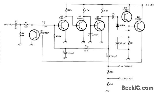
For reference, here's the circuit again (sources: https://archive.org/stream/ModernElectronicCircuitsReferenceManual/Markus-ModernElectronicCircuitsReferenceManual#page/n50/mode/1up and http://www.seekic.com/circuit_diagram/Basic_Circuit/Digital_Circuit/70_dB_GAIN_WITH_15_V.html).
Case 1: Observations when listening with a high-Z piezoelectric earphone
First, the very high headphone-level output from a portable radio was connected to to the input of the AGC amp and the volume set to maximum. Approximately 60 microamps of AGC current flowed into the base of the attenuator transistor. Again, this corresponds reasonably well to an LTspice simulation that showed a maximum of about 50 microamps of AGC current (when the amplifier was fed with a massive 10-volt peak-peak signal).
Observations:
- Connecting a high-impedance piezoelectric earphone to AGC amplifier output (either "hi" or "lo" output) did not affect the AGC current.
- Distortion was always present at any AGC level compared to taking the audio output directly from the radio. In particular, the low-frequency bass notes of music seemed the most distorted.
- Distortion was acceptably low (tolerable music listening) for input signal levels that resulted in AGC current of up to 50 microamps.
- Distortion became unacceptably high (clipping distortion) for higher signal level that result in more than 50 microamps of AGC current.
- Even when increasing the input signal levels to maximum, the output signal levels never got uncomfortably or dangerously loud, because the amplifier would simply clip the output signal.
Case 2: Observations when listening with low-Z headphones
As in the previous case, before observations began, the very high headphone-level output from a portable radio was connected to to the input of the AGC amp and the volume set to maximum. Approximately 60 microamps of AGC current flowed into the base of the attenuator transistor.
Observations:
- Connecting a low-impedance (32-ohm) set of consumer headphones to the "hi" output of the AGC amplifier immediately resulted in a decrease in AGC current of about 10 microamps.
- Distortion was noticeably higher than with Case 1 for all levels of AGC current.
- Sometimes there seemed to be an AGC pumping effect, where the AGC would seem to work briefly (leading to a reduction in distortion), then after about a second the AGC would become ineffective (leading to clipping distortion). This cycle would repeat itself every few seconds.
- Connecting the low-Z headphones to the "lo" output of the AGC amplifier produced only barely-audible output, but did not reduce the AGC current.
- Connecting the "lo" output of the AGC amplifier to an external commercially-bought headphone amplifier resulted in acceptably-high volume and acceptably-low distortion of approximately the same quality as in Case 1.
- Even when increasing the input signal levels to maximum, the output signal levels never got uncomfortably or dangerously loud, because the amplifier would simply clip the output signal.
Case 3: Observation of the effect of supply voltage
The original C. Hall circuit was designed for 1.5 volts, but I am running it off of 1.2 volts (and with different transistors). Increasing the supply voltage to 1.5 volts noticeably increased the AGC current, which reached more than 100 microamps (the maximum safe current of the meter) at only mid-level input signal levels (corresponding to a mid-level setting of the volume control on the external radio serving as the audio source). Again, this agrees in broad terms with an LTspice simulation that shows 1.3 mA of AGC current flowing when the supply voltage is 1.5 volts and the input voltage is 1 volt peak-peak. For an input voltage of 10 volts peak-peak the simulated AGC current goes even higher to 3.7 mA.
When using a 1.5 volt supply, the distortion-free dynamic range was increased compared to the 1.2-volt case. Furthermore, overall distortion was decreased at all levels of AGC current; the output audio sounded cleaner (for all levels of input signal) than when a 1.2-volt supply was used.
Discussion
For Case 3, we can explain the increased AGC current as follows. Increasing the supply voltage allows a higher control voltage to develop at the emitter of the detector transistor (Q5 in C. Hall's original diagram). This higher control voltage provides more electromotive force to overcome the threshold voltages of the two silicon diode junctions through which the control current must flow (the from the Q5 base, through the Q5 base-emitter junction and the Q1 base-collector junction, to ground). With only 1.2 volts of supply voltage, the maximum control voltage is also 1.2 volts, which is only barely enough to overcome the threshold voltage of two silicon diode junctions, each having an approximately 0.6 volt voltage drop (or possibly even more).
Though I was able to observe some degree of acceptably low-distortion AGC action, the low level of the control voltage -- only just enough to overcome the diode junction threshold voltages -- means that 1.2-volt operation may depend on the manufacturing tolerances of the particular transistors used for Q5 and Q1. In an unlucky case, it may be that the Q1 and Q5 junction threshold voltages are on the high side (closer to 0.7 volts), which will restrict the amount of AGC current that can flow and lead to distortion.
My current hypothesis to explain less AGC current leading to distortion is that with an insufficient AGC current, high input voltages are no longer able to activate the attenuator transistor Q1, meaning that the high voltages drive the amplifier into clipping.
For Case 2, distortion introduced by the low-Z headphones connected to the "hi" output of the AGC amplifier, I think there are several mechanisms at play. One mechanism is the reduction of the AGC current (that occurs when connecting low-Z headphones). As mentioned above, this likely causes clipping distortion in the amplifier. However, the situation is more complex because of the observed AGC pumping effect (Case 2, observation 3). I have no explanation for the pumping, but I did notice that increasing the emitter capacitance of Q5 (the detector transistor) from the original 10 uF to 110 uF reduced the AGC pumping. It also, of course, increased the AGC recovery time.
Though I don't have a clear explanation for the pumping mechanism, the lesson is clear: do not connect a low-Z load to the "hi" output of this AGC amp.
It is likely that the original circuit designer intended the output terminal labeled "hi output" to be used as a "high-impedance" output, but I had mistakenly interpreted it as a "high-level" output suitable for driving low-impedance loads. Unfortunately, neither reference above contains a detailed explanation of the circuit, which led to my confusion.
Conclusion and future work
When driven with a headphone-level signal source, the C. Hall AGC circuit can produce barely acceptable levels of low-distortion-output when running off of a supply voltage of 1.2 volts. A 1.5-volt supply gives less overall distortion and a wider dynamic range. In any case the output impedance of the AGC circuit should be properly matched to its load.
Since my receiver designs mandate the use of a 1.2 volt supply (to allow use of rechargeable cells and possible in-situ charging), I will proceed with connecting the 1.2-volt version of the AGC circuit to my regenerative receiver. Though the dynamic range of AGC action is limited, it is present and noticeable, and I expect that even the limited AGC action will be useful when scanning the shortwave spectrum for weak signals. Furthermore, the low supply voltage causes the amplifier to clip if excessively large input signals are encountered, meaning that the primary purpose of the AGC amplifier -- hearing protection -- is fulfilled.
Now that I have again confirmed the viability of the AGC amplifier, the next problem to solve is the unwanted oscillation that occurs when connecting up the preamplifier stages between the regenerative receiver and the AGC amplifier.
Update 2015-12-10
It's working with my regenerative detector, and it's working well. Tuning my regen across a wide frequency range has never been so pleasant! Distortion is well within acceptable ranges and the AGC action is clearly working, allowing me to hunt for weak signals while protecting my ears when tuning across a powerful SWBC signal. More details in a future post.
0 件のコメント:
コメントを投稿